

SKEMA RANGKAIAN UPS MINI
UPS (Uninterruptible Power Supply), is used to anticipate the power off. Despite UPS
Reliable not the original, this series of little means, merakitnnya How do I ...?
Simple and easy. The cost is relatively cheaper to buy rather than the original UPS.
What about the components that are required? Many sold in electronic stores. Thus you
will be losers if they do not try merakitnya.
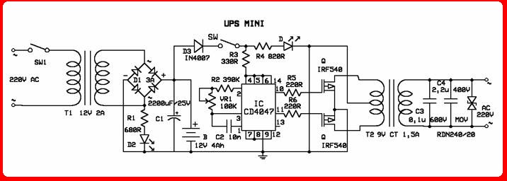
Output series UPS has a power of 1.5 W. Before the main series of the withdrawal there
is a series of mini adapter that has a voltage between 9V/12V with strong currents of
500mA. Voltage generated is used to operate the series and fill the battery. UPS is
designed to keep electronic devices can run even if the electricity off.
How to Work??
When the inverter is run with the AC input, and a change in DC voltage. At the output
penyearah used to fill the battery. When the power fails or the electric current
extinction occurs, flow to the dc voltage inverter, which then generate the output AC
voltage inverter (more details, see picture).
series of connected around the CD4047 IC multivibrator that operates at a frequency of
50 Hz. Multivibrator Q output of this drive MOSFETs IRF540. Outout inverter direduksi
and filtered using a MOV (Metal Oxide Vasitor). Tranformer used is 9-0-9, 1.5A. Two LED
(d6 and D7) is used as an indicator whether the main voltage or baattery that are
working.
UPS (Uninterruptible Power Supply), is used to anticipate the power off. Despite UPS
sehandal not the original, this series of little means, merakitnnya How do I ...?
Simple and easy. The cost is relatively cheaper to buy rather than the original UPS.
What about the components that are required? Many sold in electronic stores. Thus you
will be losers if they do not try merakitnya.
Output series UPS has a power of 1.5 W. Before the main series of the withdrawal there
is a series of mini adapter that has a voltage between 9V/12V with strong currents of
500mA. Voltage generated is used to operate the series and fill the battery. UPS is
designed to keep electronic devices can run even if the electricity off.
How to Work Series
When the inverter is run with the AC input, and a change in DC voltage. At the output
penyearah used to fill the battery. When the power fails or the electric current
extinction occurs, flow to the dc voltage inverter, which then generate the output AC
voltage inverter (more details, see picture).
series of connected around the CD4047 IC multivibrator that operates at a frequency of
50 Hz. Multivibrator Q output of this drive MOSFETs IRF540. Outout inverter direduksi
and filtered using a MOV (Metal Oxide Vasitor). Tranformer used is 9-0-9, 1.5A. Two LED
(d6 and D7) is used as an indicator whether the main voltage or baattery that are working.
INVERTER WITH IC 555

Series of DC-AC inverter produces AC output voltage as voltage net. IC 555 configured as a low frequency oscillator. Frequency can be changed from 50 to 60 Hz with a frequency potensio meter change R4.
This DC-to-AC inverter schematic produces an AC output at line frequency and voltage. The 555 is configured as a low-frequency oscillator, tunable over the frequency range of 50 to 60 Hz by Frequency potentiometer R4.
The 555 feeds its output (amplified by Q1 and Q2) to the input of transformer T1, a reverse-connected filament transformer with the necessary step-up turns ratio. Capacitor C4 and coil L1 filter the input to T1, assuring that it is effectively a sine wave. Adjust the value of T1 to your voltage.
The output (in watts) is up to you by selecting different components.
Input voltage is anywhere from +5V to +15Volt DC, adjust the 2700uF cap's working voltage accordingly.
Replacement types for Q1 are: TIP41B, TIP41C, NTE196, ECG196, etc. Replacement types for Q2 are: TIP42B, TIP42C, NTE197, ECG197, etc. Don't be afraid to use another type of similar specs, it's only a transistor... ;-)
Parts List:
R1 = 10K
R2 = 100K
R3 = 100 ohm
R4 = 50K potmeter, Linear
C1,C2 = 0.1uF
C3 = 0.01uF
C4 = 2700uF
Q1 = TIP41A, NPN, or equivalent
Q2 = TIP42A, PNP, or equivalent
L1 = 1uH
T1 = Filament transformer, your choice
If the whole thing is working, good. If not, relax and don't get frustrated. Do the following checks:
1. You have connected the filament transformer in REVERSE yes?
2. If not, disconnect the power and reverse. If you have, disconnect the transformer and measure the voltage after L1 and ground.
3. Just in case, GROUND for this circuit is same as negative (-).
4. Q1/Q2 are oposites, e.i. npn/pnp.
5. Is your 555 perhaps defective? Disconnect R3 from pin 3 and check pin 3 for a pulse.
6. Check your transistors to make sure they are not defective.
Error fix: Pin 7 and 2 were reversed. Original pinout was correct.
source skema-rangkaian-elektronika.blogspot.com
No comments:
Post a Comment