


The core of this construction is 16-Bit Stereo Digital-To-Analog Convertor with USB interface PCM2702.
PCM2702 needs only few additional parts to work. The schematic is not complex. Sound card can be powered directly from USB port (jumper W1) or from external power supply (jumper W3). PCM2702 needs two power supply 3.3V (3V-3.6V) and 5V (4.5V-5.5V). I used fixed output voltage LDO TPS76733Q for 3.3V (IO2) and adjustable output voltage LDO TPS76701Q for 5V (IO3). Both LDO are produced by TI, I used this because I had it in my drawer. Any similar LDO can be used. Output voltage of IO3 should be set to little bit lower than input voltage to allow LDO good stabilization, in my case output voltage is set to 4.8V. Output voltage can be set by adjustable resistor R33. In case of low power supply, IO3 can be shorted by jumper W3. LED D3 signalizes power on.
Small ferrite beads are placed before all power pins of PCM2702 and in Vbus and GND of USB. These small beads reduce high frequency hum. I had a problem find this small SMD ferrite beads in local stores but finally I acquire few of them from old hard drive. They are not absolutely necessary, you can use zero ohm resistors instead of them.
Low-pass filter is placed in output signal path to reduce sampling frequency. An OPA2353UA dual op amp is configured as a stereo 2nd-order low-pass filter. Led diode D1 is illuminated when PCM2702 plays audio data received from the USB bus. Led diode D2 is illuminated when USB bus suspends audio data transmission to the PCM2702.
IC 4069 Alternating On-Off Switch Circuit
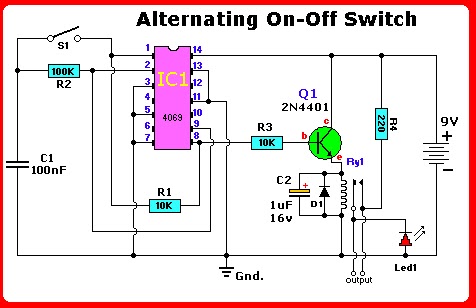
Get the circuit instead of a standard on-off switch. Switching is very gentle. If we don’t use the PCB, connect unused input pins to an appropriate logic level (’+’ or ‘-’). Unused output pins *NEED* be left open!
On the Print Circuit Board this has completed already . One step ’push’ activates the relay, another ‘push’ de-activates the relay.
IC1 (the 4069) is a regular Hex-inverter type and is constructed with MOS P-channel and N-channel
enhancement mode devices in a single monolithic structure.
Accessories List
R1 = 10K
R2 = 100K
R3 = 10K
R4 = 220 Ohm (optional)
C1 = 0.1µF, Ceramic (100nF)
C2 = 1µF/16V, Electrolytic
D1 = 1N4001
Led1 = Led, 3mm, red (optional)
Q1 = 2N4401 (see text) IC1 = 4069, CMOS, Hex Inverter (MC14069UB), or equivalent
S1 = Momentary on-switch
Ry1 = Relay )
Description of circuit.
It is going to operate on voltages from 3 to 18 volts, but most applications are in the 5-15 volts. Although the IC1 4069 contains protection circuitry against damage from ESD , use common sense when handling this device. Depending on your application you may want to use an IC-socket with IC1. It makes replacement easy if the IC ever fails. The IC is CMOS so watch for static discharge! You can use any type of 1/4 watt resistors including the metal-film type.
The type for D1 in not critical, even a 1N4148 will work. But, depending on your application I would suggest a 1N4001 as a minimum if your relay type is 0.5A or more. Any one in the 1N400x series diodes will work.
Any proper replacement for Q1 will work, including the european TUN’s. Since Q1 is just a driver to switch the relay
coil, almost any type for the transistor will do. PN100, NTE123AP, BC547, 2N3904, 2N2222, 2N4013, etc. will all work for the relays mentioned here. For heavier relays you may need to change Q1 for the appropriate type.
For C2, if you find the relay acts not fast enough, you can change it to a lower value. It is there as a spark-arrestor together with diode D1.
For the relay I used an 8 volt type with the above circuit and a 9 volt battery. Depending on your application, if the current-draw is little, you can use a cheap 5V reed-relay type. Use a 8V or 9V relay type if your supply voltage is12V. Or re-calculate resistor R3 for a higher value.
The circuit and 9V will work fine and will pull the relay between 7 and 9 volt, the only thing to watch for is the
working voltage of C2; increase that to 50V if you use a 12V supply.
The pcb was designed for an Aromat/Omron relay, 12V/5A, #HB1-DC12V. You can easily re-design the relay pads on the PCB for the relay of your choice. If you wish to use something you already have, and you don’t want to re-design the PCB, you can glue the relay up-side-down on the pcb and wire the relay contacts manually to the pcb-holes or directly to your application. Use a 2N2222 transistor for Q1 if your supply voltage is higher than 9V and/or your relay is heavy duty, or doesn’t want to pull-in for any other reason.
Again, the pcb drawing is not to scale. Use ‘page-setup’ to put the scale to 103% for a single pcb, vertically, and your scale should be correct. I use a laser printer and so I don’t know if this scale of 103% is for all printers. Tocheck, print a copy onto regular paper and see if the IC pins fit the print. If so, your copy is correct. If not,
change the scale up of down until a hardcopy fits the IC perfectly.
The Led is nice for a visual circuit indication of being ‘on’. For use with 12V supply try making make R4 about 330ohms. The LED and R4 are of course optional and can be omitted. Your application may already have some sort ofindicator and so the LED and R4 are not needed.
sumber skema-rangkaian-elektronika.blogspot.com
No comments:
Post a Comment