SKEMA RANGKAIAN AMPLIFIER

MELAYANI PERBAIKAN TV DAN PERANGKAT ELEKTRONIK LAINNYA. ALAMAT JL.RAYA KARANG KEMIRI RT 01/RW 06 PURWOKERTO TELP. 082329735432
Showing posts with label Charger Otomatis. Show all posts

Thursday, June 9, 2011

Skema Rangkaian Elektro


Kedua sirkuit yang multi-range timer menawarkan jangka waktu sampai 24 jam dan seterusnya. Keduanya pada dasarnya sama. Perbedaan utama adalah bahwa ketika waktu habis, Versi 1 energi pada relay dan Versi 2 de-memberikan energi itu. Yang pertama menggunakan daya yang lebih kecil, sementara timer sedang berjalan, dan yang kedua menggunakan daya yang lebih kecil setelah timer berhenti. Pilih satu yang paling sesuai dengan aplikasi Anda.
The Cmos 4060 adalah counter biner 14 bit dengan built in osilator. Osilator ini terdiri dari dua inverter terhubung ke Pins 9, 10 & 11; dan frekuensi diatur oleh R3, R4 & berkedip C3.The Led hijau sedangkan osilator berjalan: dan IC menghitung jumlah osilasi. Meskipun sedikit 14 counter, tidak semua bit dapat diakses. Mereka yang dapat dicapai akan ditampilkan pada gambar.

 Audio Ampifier Khusus Untuk Gitar


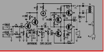
This is a circuit of an audio amplifier for the guitar. This circuit can reproduce a Combo amplifier of the type very common in the 'Sixties and the' Seventies of the past century. It is well suited as a guitar amplifier but it will do a good job with any kind of electronic musical instrument or microphone.
5W power output was a common feature of these widespread devices due to the general adoption of a class A single-tube output stage (see the Vox AC-4 model). Furthermore, nowadays we can do without the old-fashioned streetcars VIB-feature frequently included in those designs.Read More...


Most battery chargers cannot be left connected to the battery for long periods of time as over-charging and consequent battery damage will occur. This add-on circuit is placed in series with the battery being charged and is powered by the battery itself. In effect, the circuit uses a high-current Mosfet to control the charging current and it turns off when the battery voltage reaches a preset threshold. Power for the circuit is fed from the battery to 3-terminal regulator REG1 which provides 8V .Read More...

Charger Otomatis


Most battery chargers cannot be left connected to the battery for long periods of time as over-charging and consequent battery damage will occur. This add-on circuit is placed in series with the battery being charged and is powered by the battery itself. In effect, the circuit uses a high-current Mosfet to control the charging current and it turns off when the battery voltage reaches a preset threshold. Power for the circuit is fed from the battery to 3-terminal regulator REG1 which provides 8V.

Rangkaian Automatic 12V Battery Charger

LED1 indicates that the battery is connected and that power is available. The 555 timer IC is configured as an astable oscillator running at approximately 100kHz. It feeds a diode pump (D1 & D2) to generate adequate gate voltage for Mosfet Q3, enabling it to turn on with very little on resistance (typically 14 milliohms). With the Mosfet turned on, current flows from the charger's positive terminal so that charging can proceed. The battery voltage is monitored by 10kO pot VR1.

When the wiper voltage exceeds the conduction voltage of zener diode ZD1, transistor Q1 turns on and pulls pin 4 (reset) low to switch off the 555 and remove gate drive to the Mosfet. This process is progressive so that the cycle rapidly repeats itself as the battery charges. Eventually, a point is reached when the battery approaches its charged condition and the cycle slows right down. Transistor Q2 and LED2 function as a cycle indicator. When the battery is under charge, LED2 appears to be constantly on. When the battery is fully charged, LED2 briefly flicks off (charging) and returns to the on state (not charging) for a longer period.

Source http://www.extremecircuits.net.
Free counters!