


Here is a simple subwoofer filter circuit that can be powered by a 12V DC. This circuit
is very useful in automotive applications subwoofer. The circuit is a low pass filter
whose pass frequency can be set between 60 to 160 Hz
Subwoofer Filter Circuit Using Op-Amp TL072
Op-Amp TL072
The circuit is built around the TL072 dual op amp IC BIFET. Of the two operational
amplifiers inside the chip, IC1A is wired as a buffer. The left and right audio inputs
after mixing is fed to the input of the IC1A using the DPDT switch S1. Switch S1 is the
phase control switch which can be used to make the subwoofer in phase with other
speakers. When S1 is in position 2, 180 degree phase shift will be induced.POT R7 can be
used for controlling the level. IC1B forms the low pass filter whose pass frequency can
be controlled by adjusting the dual gang POT R13.
Note:
The circuit can be powered from 12V DC.
C5 and C6 must be polyester capacitors.
POT R13 can be used for adjusting the pass frequency.
POT R7 can be used for adjusting the level.
Source skema-amplifier.blogspot.com
12 volt DC Power Supply from USB port
The circuit given below infact is a 5 volt to 12 volt converter. It uses the 5 Volts
from USB port and converts it to 12 volts DC with the help of IC LT1618.
Description :
Using this circuit we can convert 5V DC from the computer USB port to 12V DC and a
circuit like this will find a lot of application in USB powered systems. The heart of
this circuit is IC LT1618 which is a constant current, constant voltage boost converter.
The IC has a wide input voltage range of 1.8 to 18V DC and output voltage can be up to 35V DC.
In the circuit resistors R1, R2 sets the output voltage. Pin number 9 is the shutdown
pin, less than 0.3V to this pin will shut down the IC. Pin number four is the current
sense adjust pin. The current sense voltage can be reduced by applying a DC voltage to
this pin. If this adjustment is not needed connect this pin to ground and you can omit
components R3, R5 and Q1.
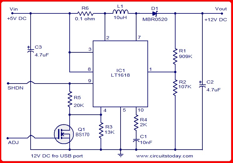
Circuit diagram of 12 volts dc power supply:
Circuit Diagram-12Volts DC power supply from USB port
Notes :
C2 and C3 must be rated at least 15V.
Less than 0.3V at the shutdown pin will shutdown the IC.
Output voltage is governed by the following equation R1 = R2 ( (Vout /1.263V) -1).
Read more: http://www.circuitstoday.com/12v-from-usb-port#ixzz1P9sMcj2v
No comments:
Post a Comment