

Driver Lampu Neon 8 watt
1KHz.The oscillator is wired so that saturation condition of the transistors are
prohibited.This adds on to the efficiency of the circuit.The circuit produces a clean
sine wave with very less noise.
Circuit diagram with Parts list.
Notes.
Use a 12 V battery as the DC voltage source.
Use a 8W florescent lamp as load.
The winding details(no of turns) are given in the circuit.Use 0.8 mm dia enameled
copper wire for primary and 0.4 mm dia enameled copper wire for secondary.The core can
be a ferrite core.The primary should be wound first and secondary on top of it.
Read more: http://www.circuitstoday.com/8w-flouroscent-lamp-driver#ixzz1PBFqzXxV
Lampu Indikator Panggilan Masuk Phone
Read more: http://www.circuitstoday.com/category/mobile-phone-related#ixzz1PBDBkK7F
The two transistors (2Sc 1983) with associated components forms a oscillator aroundHere is the schematic of a simple flouroscent lamp driver circuit based on two transistors.The circuit uses capacitive ballasting for driving the tube.An 8 W standard flouroscent tube can be efficiently driven using the circuit.

1KHz.The oscillator is wired so that saturation condition of the transistors are
prohibited.This adds on to the efficiency of the circuit.The circuit produces a clean
sine wave with very less noise.
Circuit diagram with Parts list.
Notes.
Use a 12 V battery as the DC voltage source.
Use a 8W florescent lamp as load.
The winding details(no of turns) are given in the circuit.Use 0.8 mm dia enameled
copper wire for primary and 0.4 mm dia enameled copper wire for secondary.The core can
be a ferrite core.The primary should be wound first and secondary on top of it.
Read more: http://www.circuitstoday.com/8w-flouroscent-lamp-driver#ixzz1PBFqzXxV
Lampu Indikator Panggilan Masuk Phone
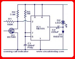
Description. This circuit can be used to escape from the nuissance of obile phone rings when you are at home.This circuit will give a visual indication if placed near a mobile phone even if the ringer is deactivated. When a call is coming to the mobile phone, the transmitter inside it becomes activated.The frequency of the transmitter is around 900MHz.The coil L1 picks up these oscillations by induction and feds it to the base of Q1.This makes the transistor Q1 activated.Since the Collector of Q1 is connected to the pin 2 of IC1 (NE555) , the IC1 is triggered to make the LED connected at its output pin (pin 3) to blink.The blinking of the LED is the indication of incoming call. Circuit diagram with Parts list. Notes. The coil L1 can be made by making 150 turns of 36 SWG enameled copper wire on a 5mm dia plastic former.Or you can purchase a 10 uH coil from shop if available. The circuit can be powered from a 6V battery. Assemble the circuit on a good quality PCB. C1 & C3 are to be polyester capacitors. The electrolytic capacitor C2 must be rated 10V.
Read more: http://www.circuitstoday.com/category/mobile-phone-related#ixzz1PBDBkK7F
No comments:
Post a Comment