This is just another 20W audio amplifier circuit , but this time based on the LM1875 audio amplifier IC from National Semiconductors. With a 25V dual power supply LM1875 can deliver 20W of audio power into a 4 ohm speaker. The LM1875 requires very less external components and has very low distortion. The IC is also packed with a lot good features like fast slew rate, wide supply voltage range, high output current, high output voltage swing, thermal protection etc. The IC is available in TO-220 plastic power package and is well suitable for a variety of applications like audio systems, servo amplifiers, home theatre systems etc.source :circuitstoday.com.
The circuit as explained by Rakesh:
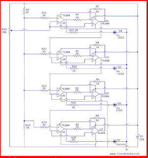
The design came from the interest of finding a new technique of analog to digital conversion. The two types of ADC (Analog to Digital Converter) that inspired me in the development of this circuit are Flash Type ADC and Successive Approximation Type ADC. The Flash Type ADC is the fastest ADC available in the market (highest sampling rate 120 Msps) but it uses a huge number of OP-AMPS. On the other hand Successive Approximation Type ADC uses fewer components but its speed is dependent upon the clock frequency provided to it. I was looking for a technique that can give a trade-off between this two, the result of which is this circuit.
Construction
The working of this circuit is similar to that of decimal fraction to binary fraction conversion. For this purpose, the circuit amplifies a signal and compares it to a reference voltage. The circuit can be divided into a number of stages. Number of stages can be increased or decreased according to need. Each stage contains two OP-AMPs(TL084). One of them (OP-AMP at the left side) is used for comparison purpose. The other (OP-AMP at the right side) is used as a non-inverting amplifier with a fixed gain (EXACTLY 2). The input voltage is connected to the non-inverting pin/terminal of each OP-AMP. The digital output is obtained from the output of the comparing OP-AMP and the output of the amplifier OP-AMP is fed to the input of the next stage. To obtain a reference voltage, two resistors are used.
Working
An input voltage is applied. The OP-AMP used as a comparator compares the input voltage with the reference level. If it exceeds a certain reference level, the comparator output goes high and there is amplification along with subtraction operation is performed by the amplifying OP-AMP. If the input voltage is less than the reference voltage, only the amplification operation is performed. The output of the amplifier OP-AMP is inherited to lower stages.
The output of my interest is the outputs obtained from the comparator OP-AMPs. They together represent binary number.source :circuitstoday.com


No comments:
Post a Comment